I finished a new project! It is a Quiz Buzzer System. I gave it a name, a horrible name, the BnB-0x7DA.
A friend of mine asked me to build this a while ago. My god, it's been nearly a year he first spoke of this! The system he had in mind needed to do only a few things: "When a button is pressed a light goes on (matching the button) and a sound is played. Oh, and could you display the person who triggered it on the screen too?"
The prototype
The first step: make a prototype. It looked something like this:
An Arduino to implement the logic of the lights and the communication with an application on a PC via USB and a few shift registers. The shift registers were required because I needed to control 16 LEDs (not enough pins on the Arduino to do that).
I also did something most people find unusual: I prototyped the software as well (most software prototypes end up being the final product). The application communicating with the arduino was written in Processing. It had only the basic functionality, but it clearly showed the idea was feasible and was a good way to show to my friend how I interpreted his "specs". The eventual application would be written in Qt / C++, more on that below.
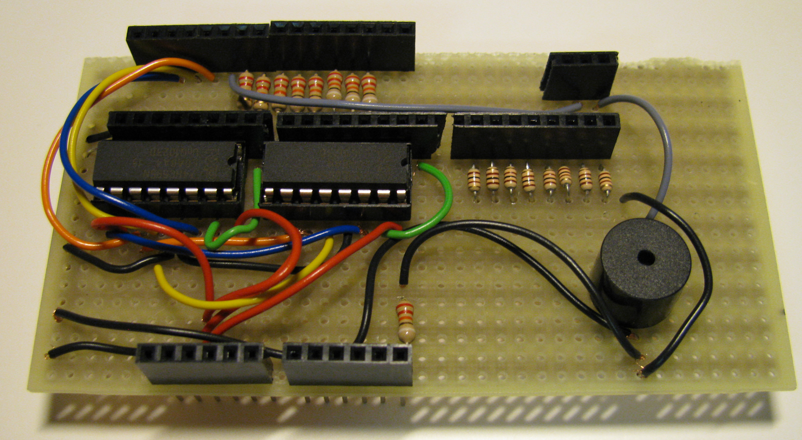
The shield
I decided it was time that I made a decent Arduino-type shield, instead of my usual big mess of wires. I'm pretty pleased with the result. It just fits right on top of an Arduino, brilliant! I can also recommend using a 2-hole-per-strip stripboard, it works really well for connecting ICs with one another.
The drilling
As soon as the electronic core was finished, it was time for the drilling. Oh boy, did I drill: 17 holes in the top cover, 6 in the bottom cover, 2 of those had to be rectangular shaped, which is a special kind of hard (drills don't come in rectangular shapes).
The wiring
To prevent messy internal wiring, I used flat cable (re-used some old IDE cable). Again, very pleased with the result.
The buttons
Next up: the buttons. My friend and I decided to come up with something other than the usual square-box-with-a-button-on-top design. So we decided to use wooden handles. These wooden handles would be fitted with illuminated buttons. (Did this just start to sound really expensive?) Not an easy thing to do, fit buttons into wooden handles. Here are some pictures of the process.
To control both a button and an LED via only 2 wires I needed a few electrical components on the buttons themselves. Luckily, these components were small enough. So they could be fitted right between the leads of the button. (The diameter of a button is 8mm.)
The BnB-0x7DA
So there you go, those were the hardware steps required to finish the project. The result can be admired in the image below: 8 player buttons, one reset button on top of the case, one button is connected to the side of the case to also function as a reset button, one spare button on the left and one toggle switch on the right to enable or disable the buzzer. Between a handle and a connector there is about 10m of cable. Totalling more than 100m of cable in this picture! Notice the nice blue and green lights :)
The software
For the software side of things, I made an application with Qt. It has a very good IDE and a clean API. It's especially easy to create decent GUIs in Qt. GUI code tends to become really messy, really fast, but Qt manages to encapsulate the messy part of GUI code in a generated source file.
The application did not need to do much. Every button is attached to a name and a sound. If enabled, this sound is played when the player presses his button first and his name shows up on the screen. The application also supports teams of players, saving and loading, auto detection of the serial port and a basic score system.
I tried some experimental GUI design. Not sure if it is æsthetic, but it definitely is user friendly.
The conclusion
Although, technically, this wasn't one of the hardest projects I have done, it surely wasn't easy. The main goal was to finish a professionally looking product which is easy to use and somewhat durable (this remains to be seen). Thomas Edison said "Success is 10 percent inspiration and 90 percent perspiration". This is definitely the case with this project. Like I said, technically, not the most difficult, but I put more time in this than any other project so far. And it was totally worth it.
Tuesday, August 17, 2010
Wednesday, October 21, 2009
Processing

You can just jump in with little or no programming experience and have a GUI, 3D or a network application up and running in no time.
The Arduino development environment is based on the Processing environment. Which is why I thought it would be a good idea to check out Processing.. and I love it :)
It's probably the best way to learn programming... then again, you will probably end up hating all other development environments if you are used to the ease of Processing ;)
Friday, September 11, 2009
BBox Drum Generator
The BBox Drum Generator is an Arduino-based Midi sequencer mounted inside a Banana Box. The BBox contains a few preset drumbeats. These drumbeats form the basis for a drum variation algorithm (explained here). The amount of introduced variations is controlled by the blue rotary knob.
I've created four pushbuttons by mounting LEDs on top of PCB mounted mini pushbuttons. This idea is based on this article.
The two top buttons navigate through the functions of the BBox. The two lower buttons change the value of the function. Currently only the BPM and the Drum Preset can be changed.
The BBox only generates midi messages, the sound is generated by a Roland Juno-D.
The Video
The Picture
The Guts
Big mess o' wires O_o
Next time, I'll create a proper Arduino shield.

Friday, September 4, 2009
Drum Variation Algorithm
The context
I've been experimenting a bit with the Arduino as a basic midi sequencer. A drum sequencer is a good place to start. It's easier than an actual melodic music sequencer. You can leave out the length of a note, as a drum is a one-shot sounds device.
Because allowing the user to program drum sequences himself requires an extensive interface, or a piece of software, I thought I would write a drum generator.
Wouldn't it be cool if you can just push a button and a computer/chip does the whole creative process for you?
Yes, it would. But it scares me a little bit as well.
I've started with a mechanism that chopped up existing drum sequences in pieces and reassembles them to generate new drum sequences. This could work for breakbeat style drum patterns, but most of the time it seemed to create a build up of expectations, only to leave the listener behind with an empty feeling.
The drum sequence format
Because the format in which the drum sequence is saved on the Arduino is essential to the Drum Variation Algorithm, I will explain this first.
The size of the RAM memory of the Arduino (based on an Atmega168) is small. Really small. Only 1kB. 1024 bytes. 8192 ones and zeros.
I'll just pause here for a while to let this sink in, I suggest you do the same.
Alright, if I want to use lots of data structures, I will have to make them small. The best way to make data small, is to assume as much as you can about the data in question and limit the possibilities as much as possible. So I introduced three limitations.
So if a measure has sixteen notes with four velocity levels, one measure for one instrument can be encoded in 4 bytes.
This is a typical drum notation which is used a lot online.
I've used large and small X's to indicate the velocity level.
In the datastructure I've described above, this would look something like this. (A B in front of ones and zeros is the binary representation of a number: 11 = B1011 = 0xB)
The first number defines the instrument as a midi note number. 42 is a hihat, 40 a snare drum and 36 a bass drum. The total amount of bytes needed to encode a measure of 3 instruments with a maximal resolution of 16th notes requires ... 15 bytes.
A clearer representation would be a number in base 4, but afaik this is not possible in C/C++. B11001000 would be 3020, so a hard hit on the first 16th note, nothing on the second, a medium hit on the third and nothing on the fourth.
The Drum Variation Algorithm
If you've gotten this far, the algorithm itself is actually really simple, I hope it is not too much of a let down. If it is, I will gladly remind you of Occam's Razor.
Everytime a new measure starts, each byte of the datastructure (except the instrument note numbers) is bitwise XOR'ed with a random byte (a number between 0 and 256). The actual random number being calculated is one between 0 and a variable limit [controlled by a potmeter]. If the number is greater than 255, the original byte is left alone. With this you can control the amount of introduced variations.
Why bitwise XOR? It seems good at keeping the feel of the original pattern. It introduces new notes, but an XOR is also affected by the original byte. A bitwise OR can only add notes and a bitwise AND can only take them away.
Here is a video demonstrating the algorithm, the knob controls the amount of introduced variations (it also demonstrates the BBox Drum Generator, a post about this will be here soon).
I love it when simple things give good results :)
I've been experimenting a bit with the Arduino as a basic midi sequencer. A drum sequencer is a good place to start. It's easier than an actual melodic music sequencer. You can leave out the length of a note, as a drum is a one-shot sounds device.
Because allowing the user to program drum sequences himself requires an extensive interface, or a piece of software, I thought I would write a drum generator.
Wouldn't it be cool if you can just push a button and a computer/chip does the whole creative process for you?
Yes, it would. But it scares me a little bit as well.
I've started with a mechanism that chopped up existing drum sequences in pieces and reassembles them to generate new drum sequences. This could work for breakbeat style drum patterns, but most of the time it seemed to create a build up of expectations, only to leave the listener behind with an empty feeling.
The drum sequence format
Because the format in which the drum sequence is saved on the Arduino is essential to the Drum Variation Algorithm, I will explain this first.
The size of the RAM memory of the Arduino (based on an Atmega168) is small. Really small. Only 1kB. 1024 bytes. 8192 ones and zeros.
I'll just pause here for a while to let this sink in, I suggest you do the same.
Alright, if I want to use lots of data structures, I will have to make them small. The best way to make data small, is to assume as much as you can about the data in question and limit the possibilities as much as possible. So I introduced three limitations.
- The drum pattern has a maximal resolution of 16th notes
- For one instrument, the maximal number of notes that can be played in one measure is 16
- There are only four velocity levels
- Midi allows 128 velocity levels, I've made a mapping from 0, 1, 2, 3 to 0, 40, 90, 110 respectively (off, soft, medium, hard)
- A measure consists of a maximum of three instruments
- A typical measure consists of a hi-hat, a snare and a bassdrum, but which instruments are used is configurable
So if a measure has sixteen notes with four velocity levels, one measure for one instrument can be encoded in 4 bytes.
This is a typical drum notation which is used a lot online.
I've used large and small X's to indicate the velocity level.
HH|X-x-X-x-X-x-X-x-|
SD|----X-------X---|
BD|X---------x-----|
In the datastructure I've described above, this would look something like this. (A B in front of ones and zeros is the binary representation of a number: 11 = B1011 = 0xB)
{
{ 42, B11001000, B11001000, B11001000, B11001000 },
{ 40, 0, B11000000, 0, B11000000 },
{ 36, B11000000, 0, B00000100, 0 }
}
The first number defines the instrument as a midi note number. 42 is a hihat, 40 a snare drum and 36 a bass drum. The total amount of bytes needed to encode a measure of 3 instruments with a maximal resolution of 16th notes requires ... 15 bytes.
A clearer representation would be a number in base 4, but afaik this is not possible in C/C++. B11001000 would be 3020, so a hard hit on the first 16th note, nothing on the second, a medium hit on the third and nothing on the fourth.
The Drum Variation Algorithm
If you've gotten this far, the algorithm itself is actually really simple, I hope it is not too much of a let down. If it is, I will gladly remind you of Occam's Razor.
Everytime a new measure starts, each byte of the datastructure (except the instrument note numbers) is bitwise XOR'ed with a random byte (a number between 0 and 256). The actual random number being calculated is one between 0 and a variable limit [controlled by a potmeter]. If the number is greater than 255, the original byte is left alone. With this you can control the amount of introduced variations.
Why bitwise XOR? It seems good at keeping the feel of the original pattern. It introduces new notes, but an XOR is also affected by the original byte. A bitwise OR can only add notes and a bitwise AND can only take them away.
Here is a video demonstrating the algorithm, the knob controls the amount of introduced variations (it also demonstrates the BBox Drum Generator, a post about this will be here soon).
I love it when simple things give good results :)
Blue LED Mouse
I fixed my mouse!
"Wait, what? And you are writing a post about that?"
Ok ok, not very spectacular. I agree. But I replaced the broken red LED with a blue one!
Still not excited? Ok, you may leave.
For the rest of you, here is a picture.

For those that are interested: the scroll wheel works with an infrared emitter and receiver. The infrared light is blocked and unblocked for every scroll "click". I did not know this, so I thought I'd share it with you. To be honest, I never really gave it any thought..
For people that like salvaging parts, here is a list of parts you can probably salvage from a broken optical mouse:
Mind you, it's a broken mouse. So some parts may not work :D
"Wait, what? And you are writing a post about that?"
Ok ok, not very spectacular. I agree. But I replaced the broken red LED with a blue one!
Still not excited? Ok, you may leave.
For the rest of you, here is a picture.

For those that are interested: the scroll wheel works with an infrared emitter and receiver. The infrared light is blocked and unblocked for every scroll "click". I did not know this, so I thought I'd share it with you. To be honest, I never really gave it any thought..
For people that like salvaging parts, here is a list of parts you can probably salvage from a broken optical mouse:
- Several pushbuttons
- A tiny camera with crappy resolution
- Infrared receiver and emitter
- An LED.. :)
- USB cable [with one half missing]
- Some chips, but I'm not sure if they will be helpful, or if you will be able to find datasheets
Mind you, it's a broken mouse. So some parts may not work :D
Wednesday, August 19, 2009
Arduino Midi Sequencer

I've fiddled with midi and an Arduino before, but now I have integrated an LCD as well. Which makes the whole thing almost usable !
The Arduino makes everything really easy; it has tutorials about communicating with the LCD, there are forumposts where people explain how they hooked it up to midi. It really is just a matter of putting all the elements together.
Currently, the "Arduino Midi Sequencer" only plays a simple drumbeat (with adjustable BPM). I hope to make it a programmable sequencer by adding some buttons and interfacing with some permanent storage. If that doesn't work out, I'll just make it a pre-programmed drum sequencer, which can lay down the groove while I practice guitar and/or bass :)
Friday, July 24, 2009
Little Drummer Robot
Someone made a robot that searches for a "beatable object". When the robot finds this object, it lays down a funky groove ... and I think it's brilliant.
Monday, July 13, 2009
Qt - Arduino Serial Communication
If you want to make a Qt application capable of serial communication with an Arduino, then these are some great resources to do so:
* QextSerialPort : cross-platform serial port library
* Arduino Serial reference : awesome Arduino documentation
Notes:
I had some trouble getting the QextSerialPort library to work with VS 2008, so I will just go over all steps I needed to take.
* Run this command in the QextSerialPort directory: qmake -tp vc : this will make a .vcproj file from the .pro file
* Open the .vcproj file with VS 2008
* Change the configuration type from dynamic library to static library [as the original setting did not produce a .lib file]
.. and you are ready to go.
JR
Saturday, July 4, 2009
Qt - Ogre - VS2008 Express
This post describes the steps necessary for getting Qt, Ogre and Visual Studio 2008 Express to work, as well as the code for a very basic OgreWidget.
Compile Qt with VS 2008 Express
Set up Ogre
A Qt/Ogre project in VS 2008 Express
You will need a few .pro files setting up your Qt/Ogre project.
It can all be placed into one file, but it might be convenient to split it into several files for easier reuse.
Settings.pro : Change your ogre home directory
For each project a separate project file.
MyProject.pro : the sources and headers need to be edited, obviously
This is a basic config to configure a Qt/Ogre application.
This project file assumes the Settings.pro file is one directory up.
Read more about Qmake project files: here
Now we set up the actual Visual Studio project:
File->New Project->Visual C++ ->General->Makefile Project
Go to the project properties (for All Configurations):
Configuration Properties -> NMake -> General
This will tell your Visual Studio to use qmake, which will convert the .pro files to a makefile for nmake, and to compile this file with nmake.
Qt/Ogre IntelliSense setup
Go to the project properties (for All Configurations):
Configuration Properties -> NMake -> IntelliSense
An OgreWidget implementation
I've tried to create a very basic OgreWidget which subclasses a QWidget. Most of the code was taken from a couple of the sources below, taking only the parts which are strictly necessary and leaving out all redundant code. The widget only renders the Ogre scene, it does not handle any user input.
OgreWidget.h
OgreWidget.cpp
Here is a code snippet on how to use this OgreWidget:
In a QMainWindow:
Easy, isn't it?
Now you set up the Ogre scene:
Of course your Ogre code will become much more ellaborate, but this is the minimum you need to render an Ogre scene inside a Qt Window.
I hope this is useful to someone :)
JR
Sources
Qt and VS 1
Qt and VS 2
Qt and VS 3
Qt and Ogre 1
Qt and Ogre 2
Qt and Ogre 3
IntelliSense
Compile Qt with VS 2008 Express
- Download and install Visual Studio Visual C++ 2008 Express Edition
- Download the source code of the Qt libraries
- Extract the zip to a path without spaces: e.g. C:\Qt
- Open the Visual Studio prompt: programs->visual studio 2008-> vs 2008 tools-> vs 2008 command prompt
- Go to the Qt dir
- Type: configure
- Type: nmake [this may take several hours]
- Setup path and VS 2008 directories
- Add an environment variable: QTDIR=C:\Qt
- Add to the path: %QTDIR%\bin
- Check if the previous is done right by opening a command prompt and typing: qmake [if this shows the help of this command, it is ok]
- Add $(QTDIR)\include to the VS 2008 VC++ include directories
- Add $(QTDIR)\lib to the VS 2008 VC++ library directories
Set up Ogre
- Download and install Ogre SDK for Visual C++ 2008
- Add OGRE_HOME to the environment variables: e.g. OGRE_HOME=C:\OgreSDK
A Qt/Ogre project in VS 2008 Express
You will need a few .pro files setting up your Qt/Ogre project.
It can all be placed into one file, but it might be convenient to split it into several files for easier reuse.
Settings.pro : Change your ogre home directory
win32 {
# You may need to change this include directory
OGREHOME = C:\OgreSDK
Release:LIBS += -L$$OGREHOME\bin\release
Debug:LIBS += -L$$OGREHOME\bin\debug
LIBS += -L$$OGREHOME\lib
INCLUDEPATH += $$OGREHOME\include
}
For each project a separate project file.
MyProject.pro : the sources and headers need to be edited, obviously
exists(../settings.pro):include(../settings.pro)
else:message("I can't find settings file")
CONFIG(debug, debug|release) {
LIBS *= -lOgreMain_d
}
CONFIG(release, debug|release) {
LIBS *= -lOgreMain
}
TEMPLATE += app
CONFIG += qt warn_on
SOURCES += Main.cpp OgreWidget.cpp
HEADERS += Main.h MainUI.h OgreWidget.h
TARGET = Main
win32:debug:CONFIG += console
This is a basic config to configure a Qt/Ogre application.
This project file assumes the Settings.pro file is one directory up.
Read more about Qmake project files: here
Now we set up the actual Visual Studio project:
File->New Project->Visual C++ ->General->Makefile Project
Go to the project properties (for All Configurations):
Configuration Properties -> NMake -> General
Build Command Line: | qmake && nmake $(ConfigurationName) |
Rebuild Command Line: | qmake && nmake $(ConfigurationName)-clean && nmake $(ConfigurationName) |
Clean Command Line: | nmake $(ConfigurationName)-clean |
Output: | $(ConfigurationName)/Main.exe |
This will tell your Visual Studio to use qmake, which will convert the .pro files to a makefile for nmake, and to compile this file with nmake.
Qt/Ogre IntelliSense setup
Go to the project properties (for All Configurations):
Configuration Properties -> NMake -> IntelliSense
Common Language Runtime Support | Common Language Runtime Support (/clr) |
Include search path | "$(QTDIR)\include";"$(OGRE_HOME)\include" |
An OgreWidget implementation
I've tried to create a very basic OgreWidget which subclasses a QWidget. Most of the code was taken from a couple of the sources below, taking only the parts which are strictly necessary and leaving out all redundant code. The widget only renders the Ogre scene, it does not handle any user input.
OgreWidget.h
OgreWidget.cpp
Here is a code snippet on how to use this OgreWidget:
In a QMainWindow:
m_pWidget = new QtOgre::OgreWidget(this);
//Add the widget to the QMainWindow
setCentralWidget(m_pWidget);
//uncomment code below for fullscreen
//Hide all the GUI stuff you do not want to see fullscreen
/*menuBar()->hide();
statusBar()->hide();
showFullScreen();*/
Easy, isn't it?
Now you set up the Ogre scene:
//Create the scene manager
mSceneManager = Ogre::Root::getSingleton().createSceneManager(Ogre::ST_GENERIC, "GenericSceneManager");
//Create the camera
mCamera = mSceneManager->createCamera("Cam");
//Add a viewport to the render window from the OgreWidget
m_pWidget->renderWindow()->addViewport(mCamera);
Of course your Ogre code will become much more ellaborate, but this is the minimum you need to render an Ogre scene inside a Qt Window.
I hope this is useful to someone :)
JR
Sources
Qt and VS 1
Qt and VS 2
Qt and VS 3
Qt and Ogre 1
Qt and Ogre 2
Qt and Ogre 3
IntelliSense
Thursday, July 2, 2009
Plexiglass Skybluepink Frame
I made this as another gift to a friend of mine, namely the drummer in my band (Skybluepink). It is a frame with the name of the band and two blinking leds behind it. It has an on/off switch and it runs on a 9V battery. Yes, it's not very high tech.
Score and Snap-method
One of the difficult parts in creating this, was transforming a broken piece of plexiglass I found somewhere, into the shapes I needed for this object. As it turns out, using an ironsaw is a very bad idea. The best results I got, was by scoring it with a cutterknife a couple of times and then snapping it along the groove made by the knife, hoping that it did not snap in the wrong places :)
Spray-painting
The other difficult part was the painting of the plexiglass. My buddy JD created a drawing which I cut out from a transparency sheet. I placed this shape over the plexiglass and then I spray-painted it. The problem was that a bit of the paint went under the cut-out shape, causing a lot of work the manually remove the excess paint. The best way to prevent this, is to make sure that the shape will not bend and is completely taped to the surface you are spray-painting.
The video
Some pictures


Subscribe to:
Posts (Atom)